Barrage
A Pavlov VR Mod Inspired
by Rainbow Six: Siege
employer: n/a
client: personal project
role: sole developer
published: august, 2019
Prologue
For the past couple of years, I’ve been a pretty avid player of Rainbow Six: Siege. The masterful mix of strategy, reflexes, completely destructible environments, well-designed levels, audio design, and gameplay mechanics had me captivated from the get-go.
Seeing as I’m also a VR enthusiast and experienced VR Rapid Prototyper, I try to stay on top of new releases in the VR industry. Now I had heard of Pavlov VR for a little while at this point (maybe a year or so) and I had even seen plenty of videos on YouTube showing it off, comparing it to the likes of Counter-Strike but in VR. However, the game’s lack of user-created content at the time made me think otherwise, so it drifted off of my radar.
Fast-forward a year or so and my good friend is streaming Pavlov VR on Twitch, he said he just couldn’t get enough of it. And from the looks of his stream, he really wasn’t lying. He invited me to play a few games of the custom game type Trouble In Terrorist Town with him. He’s a good friend and I hadn’t played any VR titles with him in a little while so I was happy to join and kill an hour or so hanging out with him.
Needless to say, it lasted a bit longer than just an hour as we were having a blast. “This game really has evolved. There were just generic Counter-Strike clone maps the last time I saw this game,” I told him. “Yeah, that’s because these are custom maps. They apparently have a mod kit,” he replied. “How did I miss this?” I thought to myself. Not too long after learning this newfound knowledge, I was already researching this supposed “mod kit”. Turns out, Pavlov VR is made using Unreal Engine 4, and they’ve got an engine plugin that allows for easy custom map/game type integration into the game.
Need I say more?
The Mission
At this point in time, Rainbow Six: Siege is still highly regarded as one of, if not the, most competitive and watched FPS games in the world. This is also while Pavlov VR is the #1 VR shooter on Steam. It seems like a match made in heaven, right? Well, let’s find out!
The Vertical Slice
In order to get a good idea of whether this idea is going to work, I need to create what’s called a vertical slice. I need to take what makes Rainbow Six: Siege… Rainbow Six: Siege, make it from the ground-up for VR, and confine it to a small section of a single level. By confining it to a smaller portion of a single level, it allows me to quickly iterate on the core mechanics and asset workflows that will be required to create an entire level, and ultimately prove whether this idea will work. If I deem the vertical slice worthy, then I take what I learned while creating it and apply it to the rest of the level(s).
Wouldn’t it just be awful if I created the entire level from the start, only to find out that I created all of the destructible walls incorrectly, setting me back days and possibly even weeks? I should make this quickly. After all, I am a rapid prototyper.
For the vertical slice level design, I decided I would go with replicating the basement portion of the popular House level.
The Basement Blockout
In order for me to really get this level design right, I need to be accurate with the dimensions and layout, and I’d preferably like to do that quickly so I can get to the good stuff; VR interaction mechanics. But I can’t be quick or accurate by just referencing images of the level. Why not reference the level itself using by using our good friend, photogrammetry?
Luckily Rainbow Six: Siege has a local spectator view that allows for birds-eye viewing of specific floors of a level. I’ll go ahead and open fraps, record sweeps of the basement floor at different angles and at the monitor’s full resolution/refresh rate (3440x1440@120hz in this case).

From there I’ll take that recorded video, import it into After Effects, crop out the UI elements, reduce the framerate to 5fps, and export the result as a PNG frame sequence to use with Reality Capture.

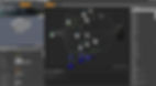
This is the point cloud result I got once reality capture is finished with reconstruction, which only took about 15 minutes thanks to a 2080Ti. But the result in reality capture looks like its transforms are pretty out of whack. I’ll go ahead and export the mesh and fix it up in 3ds Max.

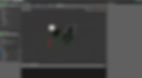
After slicing off the sides, rotating, and rescaling (using a standard 10’ wall as reference), I got this result, and it only took a total of about 30-40 minutes! Obviously, a lot of the geometry is smoothed out, jagged, and even non-existent in some areas, but thankfully I don’t really care about that. As long as the overall dimensions and layout are intact, it should act as a great starting point. Now I’ll go ahead and model/UV all of the walls, wall studs, floors, stairs, and doorways based off of this photogrammetry model.
.png)
As you can see I’ve even modeled the destructible walls along with their studs (more on this later).

In Unreal Engine 4
Placing the walls in the editor was pretty straightforward, I just copied the transforms from 3ds Max and pasted them into the UE4 editor for each wall.
Lighting
In order to properly test a level design you need to actually be able to see the level, so I did a quick and dirty lighting setup that roughly imitates that of the basement from Siege. I also made a quick first pass of each environmental mesh and made sure that the lightmap densities were relatively uniform, as seen below.

You’ll notice that there are portions of the walls that are a light brown. These are the destructible walls, which are unable to receive light baked information (only volumetric) since they’re considered movable. Because of this, you’ll also notice that there’s quite a bit of light bleed around the destructible walls. This will definitely be fixed with the use of temporary static meshes in the near future, but for now, it should be fine for testing purposes!
The Destructible Walls

Modeling
Each base (non-fractured) wall panel was basically a modified cube at the industry standard drywall thickness of ½”. However when it came to creating the wooden studs between said panels, that required a bit more work due to the fact that they too were destructible. I ended up modeling the base (non-fractured) stud frames using industry-standard stud spacing of about 16”. After I was done modeling and UVing the base studs, I used a 3ds Max plugin called FractureVoronoi which allowed me to quickly fracture the studs into the appropriate pieces, while still retaining the UVs (except for the inner UVs of course, since those did not exist before fracturing).

A large downside when fracturing a mesh with lots of spaced pieces such as stud frames is that the fracturing algorithm doesn’t take into account those spaces, which can lead to two separately spaced objects technically being considered a single object. This meant that I had to go in by hand and manually detach and reattach objects to make sure they were all properly separated pieces after fracturing.
Textures/Materials
Wall Panels
For efficiency’s sake, I only created a single drywall material for the wall panels even though ultimately there will end up being wall panels that are actually painted or even have exposed wood paneling. I made the tileable drywall material using Substance Painter and Photoshop. Painter was used for base material layering/blending, placing the nails, and stamping the serial numbers/barcodes, while Photoshop was used to create the alpha textures for the aforementioned red serial numbers/barcodes.

As for the material setup in UE4 itself for the wall panels, I ended up making sure that the textures were world aligned to allow for uniform scaling and tiling across all walls regardless of where they were placed in the world. Below you can see what the master material looks like for the drywall. You might notice there’s a TextureParameterObject named Canvas, which I’ll actually get to later in the Bullet Holes section.

Inner Material Setup
Here’s where things started to get a little tricky and actually required quite a few iterations. Since Pavlov VR uses UE4 4.21, that means that I’m still limited to UE4’s Apex destructible mesh system (Pre-Chaos destruction which is available in 4.23). This Apex destructible mesh system is pretty outdated at this point, so much so in fact that UE4 has quite a few interesting problems when it comes to niche cases like this, and they’ve acknowledged that the problems will not be fixed… so I guess I just have to deal. With that said, I was quite hell-bent on making sure that when the wall panel fractured, there should be a separate material on the inside of the panel to help further sell that this wall really is a wall. Unfortunately, UE4 4.21 was not a fan of this idea.
Upon importing a fractured mesh (the pre-fractured wall panel modeled in 3ds Max) to use as the Depth 1 mesh, UE4 would create a new material for each chunk of the imported fractured mesh, resulting in over 200 separate materials, aka draw calls, which is obviously a huge no-no. I needed there to be a maximum of 2 material draw calls per destructible mesh (One for outer, one for inner), so I started looking for different routes.
Was this reproducible in 4.20? Yes. What about 4.19? Sure is. How about 4.18? Nope! Looks like 4.18 doesn’t contain this bug as long as you fracture the mesh within the destructible mesh editor. Strange workflow, but doable. In fact, this probably saves me time as I no longer have to worry about fracturing the wall panels in 3ds Max.

So I went on to import every base (non-fractured) wall panel into a separate 4.18 project (making sure to keep the same folder structure as my 4.21 Pavlov project), fracture it, and then migrate them all over to my 4.21 Pavlov project. Due to keeping the same folder structure as the 4.21 Pavlov project, the migration was seamless, assisting in creating a smoother workflow.
The materials and fracture properties just so happened to have carried over without a hitch. Great! Although trying to fracture the mesh again in 4.21 led to reproducing the huge amounts of materials found before. So if I need to re-fracture the wall panels, I need to be sure to do so in the 4.18 project and migrate it over. Again, strange workflow, but I guess it could be worse.
Studs
There are two different types of studs in Barrage; wood and metal. The only difference between the two is indicating which walls are completely destructible. Wooden studded walls will allow complete destruction through both the panels and the studs, allowing users to walk through, given a large enough hole of course. However, metal studded walls will only allow the wall panels to be destroyed, meaning the user can use it to shoot or peak through, but not to create a new walking path.
When it came to creating the material for the studs (especially wooden) I wanted to make sure that the grain ran in the proper directions, so I made sure to rotate the UV islands in 3ds Max to correspond with the tileable wood material seen below in Substance Painter.

However, due to a slight error on my part, the few UV islands for each stud model that were supposed to have the grain running horizontally instead of vertically were not rotated, meaning the grain won’t be running in the correct direction for some pieces... Blasphemy!

Due to having gotten this far with all of the pre-fractured stud meshes in 3ds Max, I couldn’t efficiently go back and modify the UV islands without completely redoing the entire fracturing workflow over again. Time to find a workaround!

Now that looks a lot better! What I ended up doing was creating a black/white mask in Substance Painter that determined which UV islands were going to have the grain run horizontally. From there I would export the mask to be used in the corresponding material instance in UE4. Seen below is the studs master material.

In layman's terms, I’m basically taking that exported mask, multiplying it by the wood texture maps (result 1), then inverting that mask, multiplying it by those same wood texture maps, except rotated by 90 degrees (result 2), and then adding those results together to create the final material with the proper wood grain directions. I then create material instances for each studs destructible mesh and set their corresponding texture maps, seen below.


Was this workaround worth not going back and redoing the UVs for each fractured stud model? Probably not, since this method will ultimately consume slightly more video memory in the end, but it was fun to implement!
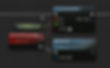
Upon finishing the wooden studs material, I went ahead and quickly created the material for the metal studs since it’s pretty straightforward. According to a little research, almost all metal studs are made out of galvanized metal, so off to Substance Source yet again. Turns out Source had the perfect match, so I went ahead and threw it into Painter and adjusted some of the parameters until I was happy with it.


Upon creating a tiling material in the editor and applying it to the metal studs mesh, this is the “final” result. It will ultimately need a second pass to show some actual edgewear, but it should do for now.
In Unreal Engine 4
When I started creating the destructible walls, I had to think a few steps ahead when it came to the scalable system that I was going to have to create to allow for easy drag-and-drop destructible wall placement in the UE4 editor.

I came to the conclusion that each destructible wall was going to consist of a wall panel for each side and wooden studs to fill in the center. From there I would be able to create a single parent actor in UE4 that would allow me to simply swap out the destructible mesh components for each child while still retaining all of the functionality found in the parent. Now I can basically just copy-paste destructible walls where need be. This allowed me to place all of the destructible walls in their respective locations within a matter of minutes. Perfect.
The Destruction
This part took quite a bit of iteration to get right, as there’s quite a few facets that go into making sure the walls are an actual fun gameplay element rather than just frustrating scenery. I don’t want the walls to be so easy to destroy that players can knock them down in a matter of seconds, ruining the flow of the gameplay. I also don’t want it to be so difficult that it completely discourages the fun of destructible environments. All the while trying to keep performance in check. After all I am developing for not just VR, but VR on lower spec hardware than my own.
I’ll go ahead and start with tweaking the fracture damage threshold for both the studs’ and panels’ destructible meshes. But first, I don’t have a baseline of how much damage the walls are taking depending on the weapon. So how do I figure this out? I’ll debug! I’ll take the damage value from Event AnyDamage, plug it into a Print String, shoot the walls in the game, and write down the values. Easy enough.
Unfortunately, when using Pavlov’s UE4 plugin to create the pak file to deploy to the game’s local directory, it packages the project in the Shipping configuration, meaning that there’s absolutely no typical debugging methods available to use while in the game itself. That definitely complicates things. Time to get creative!
Luckily UE4 has TextRenderComponents, which can actually be seen properly in Shipping configured packaged games, I just have to be sure to place them in an easy to view spot.

That appeared to do the trick. I just used the same method that I would have used with Print String, except applied it to the text component. Now I could see the damage values being applied to the wall of each weapon upon shooting at it in-game. At this point, I won’t go down the rabbit hole that is showing debug damage events. From my findings, a single bullet’s damage ranged from ~36 (pistols or individual shotgun pellets) all the way up to ~250 (Revolver or snipers) depending on range of course, since Pavlov appears to have a damage falloff system.
Alright so now that I knew that, I could start to play with some middle-of-the-road values and see what works best. After about 5 iterations of different damage values, this is what I settled on for both the studs and panels.


Damage Threshold
-
Studs: Thick wood is obviously going to be quite a bit more enduring than ½” drywall in terms of damage, so the damage that it takes to destroy a single chunk should be quite a bit higher.
-
-
Panel: This value ended up striking a pretty decent balance between fun and challenging. It won’t take a matter of seconds to create a hole large enough to walk through, but it also won’t discourage players from trying to get a peak on someone in a pinch.
Debris
Remember when I mentioned performance? Well this is where that mostly comes into play. You’ll notice how the debris parameter values are all set to zero. This means that when a chunk breaks free, that chunk can now have timeout/separation values applied to it which determine how/when it should be destroyed, therefore removing a draw call. Having physics looks nice and all, but it starts to become quite the performance hog when you have double, and sometimes even triple, digits worth of simulated objects on top of the object draw calls. So in this instance, we’re setting the debris values to zero which causes the chunks to be destroyed immediately once they take enough damage to fracture. This is applied to both the studs and the panels.
Note: These debris values will not actually work unless the flags Enable Debris, Debris Timeout, and Debris Separation are enabled alongside Debris Depth being set to 1.
Outer Stud Pieces
I figured it would be kind of strange for the player to destroy the entirety of the studs, since 1) it would leave an oddly unnatural square hole for players to walk through and 2) that would mean the insides of the accompanying walls would be visible, which would not be preferred. So I selected each outer chunk of the studs in the destructible mesh (except for the bottom once since that would prevent players from walk through) and I enabled the Do Not Damage flag. Upon clicking the checkbox, the engine crashed. Okay, I’ve had plenty of strange flukes that caused UE4 engine crashes, so I’ll just try it again. I opened the engine again, selected the chunks, and clicked Do Not Damage. It crashed. Oh boy, here we go again.
So of course I start trying older versions of the engine to see if the bug is present there as well. Luckily, my first shot trying it in 4.20 worked. I could enable the proper flags to prevent chunks from being damaged or fractured. Migrating over to my Pavlov 4.21 project also appeared to be a success.

Wall Reinforcements Setup
Wall reinforcements are a large part of Siege’s gameplay mechanics, although I won’t really be touching on that in this section, as that will be reserved for The Wall Reinforcements section. This section will briefly highlight how I’ve created a construction script system to allow me to easily, and quickly, place perfectly fitted wall reinforcement actors along all destructible walls.

I’ll try to briefly explain the overview of what’s going on in the addReinforcements function, as parts of it could start to bleed into the actual Wall Reinforcement functionality, which, again, is not the focus here.
The addReinforcements function is taking in the number of ReinforcementsPerSide that I choose from within the editor and using that number to drive ForLoops that add BP_Reinforcement_Wall child actor components at its corresponding relative location. The location is being derived from the wall dimensions found from the getWallDimensions function found below (this is being called in the construction script before calling addReinforcements).

Notice how I’m using Print String in this case for debugging. I’m actually only interested in knowing a walls dimensions in the editor, and not in the game, which still works fine here.
After adding the BP_Reinforcement_Wall child actor to BP_Destructible_Wall, I’m then getting the actor as BP_Reinforcement_Wall through casting, adding it to the reinforcementSpots array for later use, and then setting its width morph target value.

You can see me in the sped up gif above changing the ReinforcementsPerSide value in the editor and simulating the result by using a makeshift Pawn actor to simulate overlaps.
Apart from the addReinforcements function, do you remember that reinforcementSpots array that I mentioned not too long ago? Well now I’m going to use that array of all of the reinforcements, loop through them, and set their otherReinforcements array variable with the same reinforcementSpots array. This will end up allowing each wall reinforcement to know what other wall reinforcement is perpendicular to it. This will help prevent two reinforcements from being placed across from each other.
Bullet Holes
So aside from the larger destruction found in Siege, there’s also what I like to call “Preliminary Destruction” which is a form of destruction that occurs before the real destruction happens. In this case it’s bullet holes. Bullet holes should only be seen on the wall panels to assist the user in being able to peek through walls before they actually fracture the pieces they’ve damaged. This also of course helps add that extra bit of grounding in the reality I’m trying to build. Doing this will require the use of Render Targets, blueprint scripting, and vector math. Let’s take a look.
Bullet Hole Material
Remember that image of the material for the drywall with a ParameterTextureObject named Canvas? This is going to be where I “paint” (for the lack of a better term) the opacity mask. But I’m going to be dynamically painting the opacity mask with bullet holes.
Below you’ll find the material where I’m setting up what the bullet hole brush will look like by using a height map alpha that I baked in Painter using a bullet hole mesh.


Here’s that bullet hole mesh in painter that was used to create the alpha seen in the material.
Aside from that, this material also drives where and how the bullet hole texture will be painted onto the Render Target (Canvas). The parameters to really focus on here are Position, Scale, and Rotation, as those are what drives the overall functionality and appearance. The position vector parameter will basically be telling where in UV space the bullet hole should be painted. The scale and rotation parameters do exactly that, they scale and rotate the bullethole, but more on that later.
Blueprint Implementation
Next I need to actually setup this render target system in my BP_Destructible_Wall parent actor. First I’ll start by creating all of the DynamicMaterialInstances based off of the existing materials applied to each wall panel, and then assigning them to their own variables for later use. I’ll then create a DynamicMaterialInstance based off of the bullethole brush material that I just finished talking about and also assign its own variable for later use. This is all being done in my createDMIs function found in the construction script.

After this I’ll need to actually initialize the render targets on each wall panels’ DMI to allow them to be “painted” on. Here’s my InitializeRenderTargets function that’s being called on Event BeginPlay.

Once I finished initializing the render targets for the wall panels, it was then time to begin creating the actual bullet hole mask when a bullet collides with the wall. Below you’ll find the logic that is executed when Event AnyDamage is called in the Event Graph. ApplyRadiusDamage is simply being used to tell where to apply, and how much, damage to the destructible meshes and what location and radius to drive the destruction. What really matters here is the createBulletHole function where the hit location, direction, and damage are being used as inputs.


So this function is multi-faceted seeing as there’s a few things going on, aside from the color coding. The first node in the execution path is setting the scale of the bullet hole depending on the damage. So if a more powerful, high caliber, weapon is causing the damage, then the bullet hole will be larger, but only to a certain extent as I’ve clamped the value so that the holes have a minimum and maximum size.
After this you’ll find a sequence node driving four different paths, all with similar functionalities. Below you’ll also find a rather crude visualization of what’s going on in relation to the above blueprints. This is where the vector math comes in, and I’ll let my function speak for itself in that regard. What’s important to focus on here is the LineTraceComponent and FindCollisionUV nodes which are driving where the bullet hole brush will be painted onto the render target.

For LineTraceComponent, I can’t trace against the destructible mesh because it’s UVs will no longer be reliable after the first fracture. So to solve this, I’ve got the destructible mesh’s base static mesh being used as the component to trace against, as those UVs will never change. All I have to do is turn off the visibility and it acts as an invisible collider. Using line trace component also allows me to check only against a defined component, removing the off chance that the trace hits some other object in the world.
With regards to the FindCollisionUV node, it’s taking the out hit structure, using that to find where in UV space that hit occurred, and outputting its coordinates. From there I just need to input those coordinates into the Position vector parameter found in the brush DMI. Immediately after that parameter is set, I draw the brush, and all of its newly set parameters, to the Canvas render target.
Effects
Damage Decals


Below you’ll find the material graph where I’m using the mask to drive the layering of different texture properties to result in the final decal material.
Once I was finished creating the material, I then created a standalone BP_DamageDecal_Drywall actor which would contain a construction script that randomly rotates and scales the decal to break up the repetition that would otherwise arise from using a single material at the same rotation and scale. Since this functionality is in the construction script, I can actually test this out in the editor, as seen below.

Now, when the event OnComponentFracture is executed in BP_Destructible_Wall’s Event Graph, I call the spawnDamageDecal function and feed it the Location, Direction, Static Mesh component to trace against, and the decal actor I want to use (which opens the function up to when I create different types of damage decal actors for different wall types).

Before I get to the actual spawnDamageDecal function, you might notice how after the fracture occurs, I have a 0.001s delay and then I’m setting RecievesDecals to true. When I first implemented this I was scratching my head for a little bit wondering why I could see the first decal on the destructible mesh for only a split second when the destructible mesh fractured. After digging through the DestructibleComponent.cpp engine code on github, I found this handy snippet:
void UDestructibleComponent::OnDamageEvent(const NxApexDamageEventReportData& InDamageE
vent)
// After receiving damage, no longer receive decals.
if (bReceivesDecals)
{
bReceivesDecals = false;
MarkRenderStateDirty();
}
RecievesDecals is being set to false after it receives damage. So why not just set it to true every time the destructible mesh fractures? Turns out that actually works really well, but only if you set an incredibly small delay before setting it, which is what I’ve done here. Below you’ll also see what the spawnDamageDecal consists of, which is pretty straightforward.

Fracture Particles
Aside from the decals, there should also be some particles that eject from the damage location when a chunk is destroyed. This will not only help breathe a little more life into the wall destruction, but also help to hide the instantaneous disappearance of chunks upon fracturing. Implementing this was pretty straightforward, I just needed to call my spawnImpactParticle function upon fracture, which takes the desired particle, location, direction, and desired scale. Below you’ll find what the function looks like which is doing some vector math to determine the rotation and velocity at which to spawn the particle.

The Wrist Equipment Menu

Note:
These next few sections will unfortunately become progressively more summarized in detail as the blueprint logic starts to become far more dense.
In preparation for the upcoming intractable objects that I was going to have to make, I needed to create some sort of quick menu system that would allow players to quickly place/remove barricades, place wall reinforcements, pull up their camera feeds, or use a special ability (if it gets to that point). I also had to design this menu in such a way that was intuitive and didn’t require any more input than just the trigger since I wanted to keep this as platform agnostic as possible. So why not create a wrist menu that contextually opens up when you look at it, and you just use your opposite hand’s index finger as the interactor? So I went ahead and quickly mocked up a simple UMG Menu along with a quick open/close animation.


The buttons are using a dynamic UI material that I made allowing for pixel-perfect and on-the-fly border control (uniform or individual), gradient and texture support, outlines, and more. This allows for incredibly fast iteration for clean UI design, removing the need to update texture files outside of the editor.
Game Logic Intermediary
If I was going to actually implement this menu idea, let alone create highly interactable objects such as the barricades or reinforcements, then I was going to need to somehow hijack Pavlov’s Pawn with my own logic. This is where my Barrage_GameLogic_Intermediary actor comes into play.
In summary, this actor is being attached to the player’s pawn (Pavlov pawn) when the game begins. Once that happens, the intermediary actor steps through its instigator’s (the Pavlov pawn) children components until it finds motion controller components. Once it finds the motion controller components, it sets them as their own variables, and then proceeds to attach both T_Hand_R and T_Hand_L to them. The children of T_Hand_R and T_Hand_L contain the hand collision spheres, the index collision capsules, debug text components, and a WidgetComponent/WidgetInteractor which contains the aforementioned Wrist Equipment UMG Menu.
Apart from the motion controllers, I’m also finding the Pavlov pawn’s camera component (HMD), passing it to its own variable, and attaching my own collision sphere to it. This will ultimately end up being used to assist in creating the wrist menu opening logic.

Stepping through all of the pawn’s components, until finding a motion controller or camera, and attaching all of the appropriate intermediary components

Stepping through the children of the supplied motion controller to find the hand SKSH (Skeletal Mesh), and then use the output to set as its own variable for the corresponding hand.

This is where the majority of the grabbing logic occurs when it comes to interacting with the wall reinforcements and barricades. This system could definitely use some refinement to improve scalability, but since there aren’t a lot of planned interactable objects then this should be okay for now.


In the LookingAtWrist macro, I’m checking to see if both C_Menu_Focus (The collision capsule on the wrist) is colliding with C_Head (The collision attached to the HMD) and that the HMD is actually looking at the wrist within a certain threshold via dot product. The rest of this macro consists of debug text that was used to refine the threshold and check for collision.


Pretty straightforward here, although I had to make sure to use the Press Pointer Key node instead of the Press Pointer node, as they do in fact operate differently.
The Wall Reinforcements

In the LookingAtWrist macro, I’m checking to see if both C_Menu_Focus (The collision capsule on the wrist) is colliding with C_Head (The collision attached to the HMD) and that the HMD is actually looking at the wrist within a certain threshold via dot product. The rest of this macro consists of debug text that was used to refine the threshold and check for collision.
Modeling & Rigging
When it came to modeling the reinforcement, there were definitely a few key aspects to keep in mind. I needed to make sure that a single skeletal mesh (Morph targets in this case) would be used for any and all walls while also staying relatively low poly, and still carried over the characteristics that make it a distinguishable feature.

After creating several different iterations of the design of the reinforcement, this is what I landed on. I started by creating a reinforcement model that was exactly 100cm in width and then once I was happy with it, I then proceeded to duplicate it and move the vertices of each separate model such that I created two different “poses”; Open and Width, with the width pose being exactly 400cm wide. These poses would go on to serve as the morph targets that will be used for not only the wall construction script system displayed in the Destructible Walls section, but also for interacting with in VR.

Aside from the reinforcement being modeled, I also needed to model the lever along with the anchors. For the uninitiated, the “anchors” are basically the hook parts of the reinforcement that “inject” into the wall once the reinforcement placement has been completed. The anchors also serve as a useful visual indicator from the other side of the wall to indicate to attackers that the wall has been reinforced.

Here’s the lever assembly, which actually consists of three separate moving parts.

And here’s one of anchors that will be “injected” into the walls. The length of the anchor also needed to match up perfectly with the universal thickness of all destructible walls so as to make sure that they are visible on the other side of destructible walls.
Textures & Materials
When dealing with blendshape skeletal meshes, you always have to be thoughtful of how to proceed with texturing, especially so in this case. Even though I had unwrapped the UVs properly, there were still going to be portions of the mesh that would inherently stretch the UVs more so than other parts due to the nature of morph targets.
For instance, the parts of the mesh that I didn’t really need to worry about were the small anchor bases, the lever base where the hydraulic piston is located, the top metal housing, and the support beams. The other pieces such as the bottom floorpanel and especially the shutter (the flat backing) were of major importance to make sure there was no texture stretching. Needless to say I ultimately ended up going with world aligned textures in UE4 to solve this problem.

All of the different layers that went into creating the material for the wall reinforcement. Turned out quite nicely if I do say so myself.

All of the different layers that also went into creating the material for the wall reinforcement anchor.

All of the the texture layering of the lever assembly in Painter.
Then the moment came that I actually implement the material system into the project. Below you’ll find the master material graph dedicated to the entirety of the reinforcement skeletal mesh, which means it excludes the lever assembly and anchors. The anchor and lever assembly were pretty straightforward materials since they’re static.

Remember when I mentioned those parts of the blendshape skeletal mesh that were the only parts to be worried about with regards to texture stretching? Well, to summarize, in this material I’m masking those parts out and replacing them with their world aligned versions, resulting in this. No stretching on either the shutter or the floorpanel!

There’s also a scalar parameter in the same material that drives whether the material is in highlight mode or not, which is activated when the reinforcement is in its rollover state.

In Unreal Engine 4
In my opinion this is really where the fun begins! At this point I need to start working on the actual physicality and intractability of the reinforcements.
Setting Up The Collision
Since skeletal meshes inherently have a lot of moving parts, that means accurate collision can get a bit tricky, especially hard surface skeletal meshes. Since this object plays such a vital role in the gameplay mechanics, I wanted to make sure that the collision was impeccable, dare I say perfect. Luckily, the geometry of the reinforcement wasn’t all that complex, so I went ahead and created a system of separate box colliders (seen below in the actor viewport) that dynamically scale to fit all of the main pieces of the reinforcement via construction script and during runtime when it’s being interacted with.


If you pay close attention to the gif above, you can see the collision extents updating as I change the morph properties of the reinforcement skeletal mesh. I did this by referencing the vertex locations of each of the main pieces in 3ds Max and using them in the updateCollisionProperties function seen below to interpolate the box colliders’ extents.

This results in collision so vertex-perfect, that it’s almost too difficult to even see the debug lines! Perfect!
Interactions
Rollover Logic
In order for a player to even “place” a reinforcement down in front of the wall, they need to be overlapping the AreaOfActivation box collision. The RolloverLogic blueprint graph seen below is where I’m checking to make sure if a single pawn is overlapping.

If there is only a single pawn overlapping, then tell the reinforcement to highlight (rollover state), and pass itself to the WristEquipment menu. From within the passSelfToEquipmentUI function, you can see that I’m stepping through the overlapped pawn to grab a reference to the GameLogic_Intermediary actor. Once I’ve found the Intermediary actor, I grab the EquipmentMenu and set its OverlappedReinforcement variable to self (the reinforcement calling this function) and then passing to a new variable called equipmentMenu for the reinforcement actor to reference later.

Once the reinforcement has entered its rollover state, then all the user needs to do is look at their wrist menu and press the reinforcement button to place the reinforcement.

Once the user has pressed the reinforcement button in their menu, then the following PlaceReinforcement event is called in the overlapped reinforcement actor.

Upon PlaceReinforcement being called, a few different things happen. First, changeStateOfPerpendicularReinforcement is called which finds the perpendicular reinforcement actor and disables its AreaOfActivation collision, effectively disabling the entire reinforcement functionality. This is to prevent another player from placing an unnecessary reinforcement directly on the other side of the wall.

After this function is called, I then disable the highlight parameter in the DMIs of the reinforcement SKSH and lever static mesh components to bring the material to its intended look, essentially “spawning” (psychologically) the reinforcement. Following this, I unhide the placeholder hands (intended to act as guides), enable collision of all of the box colliders, and then set the Placed bool to true.
Faux Tick
To help optimize when functions are called, especially ones that need to be called almost every frame, I use something I like to call FauxTick (FakeTick). FauxTick is my workaround for creating a “Tick” event, except the event is only called at an interval that I choose. This allows me to call functions that need to be perceived as running every frame, but could in actuality be running far less often. This allows me to also use actual EventTick in tandem for vital functionalities such as motion controller interactions.
I do this by using SetTimerByEvent, enabling Looping, setting the timer interval, and then creating a “Passthrough” event that actually calls the FauxTick event. I only do this because it allows me to place the FauxTick event anywhere in the graph.

In this instance I’m using FauxTick to call important functions, but not functions that require being called every frame, such as RolloverLogic (Which is just a collapsed graph).
Opening & Closing The Reinforcement
Once the placed event has been called, causing the Placed variable to be set to true, this is now when the checkForHandsCollision and setPlaceholderHandsVisibilty functions come into play.

In the checkForHandsCollision function, I’m first checking to make sure that Placed is true, and that the left and right hands are not grabbing anything (These are being set by the Intermediary actor). If these bools are all true, then I proceed to check if the Grab collider or Lever colliders (Depending on if the reinforcement has been opened yet) are being overlapped by an Intermediary actor. If this is true, then I go on to get the overlapped Intermediary, pass it to a new variable for the reinforcement actor to reference later, and then set the Intermediary’s GrabbableObject variable to self (The reinforcement actor that’s calling this function).
After checkForHandsCollision is called, I then call the setPlaceholderHandsVisibilty function, which is really only used to set the visibility of the left and right placeholderHands, depending on which, if any or both, hand(s) is grabbing.


Once the player’s hands are overlapping the Grab collider, and they press the grip on either controller to grab, that’s when the Intermediary will take over and check the GrabbableObject if it’s a BP_Reinforcement_Wall or BP_Barricade, or none. If it’s a BP_Reinforcement_Wall, then I pass the Reinforcement actor to the CurrentReinforcement variable and then proceed to attach Pavlov’s Hand SKSH to either the housing’s attach point (T_Hand_AttachPoint_L) or the lever’s attach point (T_Hand_AttachPoint_Lever_L), depending on what state the reinforcement is in. If the attachment is successful, then I set the overlapped reinforcement’s LeftHandGrabbing bool to True.

It’s important to note that when I’m attaching Pavlov’s Hand SKSHs to the attach points, the actual motion controller components are being unaffected since the Hand SKSH is a child of the motion controllers. This allows me to achieve a better feeling grabbing system that tricks the mind a little more into thinking it’s actually grabbing something.

Now this is where I touch on the real meat-and-potatoes of the reinforcements; the logic that drives actually opening the reinforcement and interacting with the lever. Above you’ll notice what appears to be just a branch checking to make sure that the reinforcement has been placed. If it has been placed, then two collapsed nodes will be called in a sequence, Opening Logic and Lever Logic. Let’s first take a look at the Opening Logic. Also, keep in mind that this is all running on EventTick for maximum fidelity.
Opening Logic

As you can see there’s quite a bit going on in here. This is one of those portions where I’ll be doing some summarizing since getting into the nitty gritty would be pretty time consuming due to the complexity of it all.
So as long as the right and left hands are grabbing and the reinforcement is not open, then I will immediately get the starting Z location of the hands and set that to a variable, using my determineHandsStartingZ function seen below.

As soon as this happens, I will also start the timer countdown for when the reinforcement will completely reset. Afterall, I can’t have players just placing reinforcements and using them as invincible shields. This timer is also updating a DMI applied to a mesh to help visualize how much time the player has left to finish.

Immediately after those functions/timeline are called, and variables are set, I then get the normalizedHandsZLocation, which is fed into the Open variable, which then drives the morph target value for the reinforcement.

What normalizing means in this case is taking the point that the motion controllers started at when grabbing, and the maximum possible height they should be able to reach, and then turning that into a range from 0-1, which is the value range that morph targets take.

After setting the Open variable with the normalized hand location, I’m then calculating the average Z Velocity of the motion controllers and setting that to a variable. I’m get the average Z velocity of the motion controllers so that when the user lets go past the open threshold, and the timeline plays to finish off the opening of the reinforcement, then the reinforcement will finish opening at a rate that’s similar to the user’s hands. This effect helps further ground the reinforcement in reality, not to mention it helps the reinforcement opening process to feel more natural and fun to the user.
Once I get and set the velocity, I then update all of the box colliders’ properties (location and extents) via updateCollisionProperties and then set the StartedOpening bool to true. Remember, this is all running on EventTick.
Upon the user letting go, I then check to see if the current Open value equals or exceeds the threshold that I have set. If it does exceed the threshold then I call the ReleaseHands event in the Intermediary actor (which attaches the Pavlov Hands’ SKSH back to the motion controller) and finish opening the reinforcement through the use of a timeline. Once it’s finished opening, I set the IsOpen bool to true, and unhide the lever placeholder hands.

If the user lets go of the reinforcement when the Open value is less than the threshold, then I release the hands and close the reinforcement. Once the reinforcement is finished the closing, the user can grab the reinforcement again and try to finish opening it, assuming they have enough time left on the timer.

Lever Logic
Now I’ll get into one of the last pieces that will finish off the reinforcement interactions, and that’s interacting with the lever.

Once the user has finished opening the reinforcement and the bool IsOpen is set to true, then that’s when the lever logic will kick in and I start checking to see if both the left and right hands are grabbing the lever. If they are both grabbing the lever, then I get what the initial distance from the “leading hand” (the right motion controller in this instance) to the first “stage” using my getHandDistanceToPoint. In this instance, a “stage” is just a scene component that represents where the motion controller should be for that “stage” to be complete. Since there are two stages to the lever opening, there are two different scene components, as seen below.


Here’s that getHandDistanceToPont macro that I mentioned earlier. I’m just getting the distance between the stage scene component of my choice and the right motion controller along the axes of my choice. Notice how I’m converting the vector3 to a vector2 due to the fact that the rotations for this lever action only occurs on two separate axes rather than 3.
Once the initial distance variable has been set for the first stage, I then check to see if stage one is complete. If stage one is not complete, then I go on to setting the rotation of the lever by normalizing the current hand distance to the stage one scene component and feeding it into the alpha of a lerp (rotator) node. While this is happening I’m also setting the initial hand distance for stage two for when the StageOneComplete bool is set to true. You’ll also notice how I’m setting the rotation of the left hand attach point while the lever is being turned. This is to help emulate what would actually happen to your hand in reality if you were to turn a lever in this fashion, further helping to sell the effect.
As soon as the StageOneComplete bool is set to true, I just repeat the same logic that was implemented for stage one, except for the YZ axes. Also worth noting is that when the user lets go of the lever during the second stage and is past a specified distance threshold, then the hands will be released and the timeline will finish the rest of the lever closing for the user. There’s two reasons to this auto-finishing behavior. First reason being that I don’t want the user struggling to try and get their motion controllers in just the right spot to finish off the last bit of the process. The second reason is that it allows the user to sort of “toss” the lever towards the end, adding another small touch that helps with making the process enjoyable rather than tedious.
Right as the second stage is finished, then the anchors are “injected” into the wall to signify that the process is complete and the reinforcement can no longer be destroyed, modified, or reset in any way.


The reset function in its entirety.
The Barricades

Barricades are among one of the few core gameplay mechanics in siege besides destructible walls and wall reinforcements. They allow the defending team to quickly block a doorway or window to block line of sight and alert the players via audio cue when someone breaks in. Since the barricade is both intractable and destructible, this is basically going to be like combining what I learned from the walls and reinforcements into one.
Modeling & Rigging
Modeling and creating morph targets for the barricades weren’t going to be as difficult as the reinforcements as there aren’t nearly as many moving parts, but that’s not to say that there weren’t any difficulties. I needed to create a barricade for both single-wide doorways (which would also double as window barricades) along with double-wide barricades, which meant there needed to be uniformity across doorways and window frames. Luckily I had already accounted for this when modeling the doorways in the first section.

The workflow that I landed on to create the base models was first creating 3 separate wood planks for both the single and double-wide barricades. I then used bool operations to create the individual chunks on each plank, which proved to be a rather tedious task. After that I would draw random planks from the three that I created and stack them, rotat each of them 180 degrees in random axes, and then would slightly offset them on the X/Y axis to slightly misalign all of them. This would help give the effect that the were quickly assembled. Once I stacked all 14 of the planks for each barricade type, I then created the fabric strips on each side that are meant to hold all of the planks together.
After creating the base models and UVing them, I then went on to create the closed pose for each of the barricade types. These would ultimately end up being used to create the morph target, as seen below. Now it’s time to take them in Substance Painer and bring some life into them.

Texturing & Materials

Above are gifs displaying the material layering of each barricade type in Substance Painter.
Now it's time to show off the materials in UE4!

Here’s a look into the master material. You’ll notice how I have the same highlighting parameters as the wall reinforcement material. You’ll also notice how there’s that same Canvas ParameterTextureObject. That’s right, more bullet holes. Consistency is key!

Now here’s a look at the material instance which will allow me to easily swap out the texture maps. This will come in handy for the construction script found in the next section.
In Unreal Engine 4
Due to the fact that the barricades carry a lot of the same features/functionalities over from the reinforcements and destructible walls, I’ll be skimming over a fair bit. No worries though, I’ll still be including screenshots of the blueprints!
The Construction Script
So I knew that going into this that there was going to need to be a useful construction script system that would allow me to quickly place barricade actors throughout the level since they are plentiful in Siege. Ideally, the only options that I would need to have is 1) Will the barricade be placed at the beginning of the game? 2) Is the barricade type a single or double-wide? And 3) What barricade actor share this doorway/window frame? And here’s the result!

Now let’s quickly check out the construction script blueprints.

The tidy construction script where all of the necessary functions are being called.

The InitializeBarricadeProperties function where I’m setting all of the Static, Skeletal, and Destructible meshes while also setting the texture/scalar parameter values for the materials. These are all being driven off of whether the barricade is of type double or single.

Here’s where the visibility of the barricade is being determined by whether or not the PlaceOnBegin bool is set to true.

Initializing the bullet hole material.

setupTimerMesh function where I’m just changing the scale of the timer mesh to fit the width of the barricade if it’s single or double-wide.

Lastly, here’s the setupNails function, where I’m setting the nail static mesh location with its corresponding box collider.
The Destruction


Unfortunately I still had to create the destructible meshes in an older project version in order to have only a single material for the entire destructible mesh. Other than that though, it turned out great! Although, the viewport is displaying the barricades in the wrong direction due to me having them face -Y.

Aside from the destructible meshes themselves, how the barricade receives damage is a bit different from the destructible wall. Firstly, as soon as AnyDamage is called, I’m checking to see if the bullet hit outside of the “threshold”. The threshold being the chunks along the sides of the destructible mesh. If it is hitting the sides, then do nothing. The reasoning for this is because it would allow people to essentially shoot a non-destructible part of the barricade, accumulate damage to it, and then destroy it without the enemy really getting a chance to see it coming.

If the bullet hits within the threshold, then add the damage to the TotalDamage variable, apply damage to the destructible mesh, and create a bullet hole. If the TotalDamage value exceeds the threshold (The single barricade takes less damage to fully destroy when compared to the double barricade), then destroy the entire destructible mesh and call the reset function.
The Interactions

The event BeginPlay section of the event graph, which is just about identical to that of the destructible wall actor.

Initializing render target properties on event BeginPlay as seen in BP_Destructible_Wall.

The FauxTick event and what it’s driving. Again, basically identical to BP_Reinforcement_Wall.
Rollover Logic

Opening/Closing The Barricade

Check hands for collision.

The function setPlaceholderHandsVisibility.

This is the PlaceBarricade event in the event graph that’s called when the user presses the barricade button on their wrist menu. Very similar to what happens in the reinforcement actor, except if the barricade has been destroyed, then another can be placed.

EventTick where OpeningLogic is being called if the barricade has been placed.

Within the OpeningLogic graph, the majority of it is carried over from the reinforcement actor, except for a couple of new features.
As you may have noticed in the gif at the beginning of the section, a nail gun appears in the player’s hand when they’re finished opening the barricade, which requires them to place nails over the Xs in the center-left and center-right areas of the barricade to stop the timer and finish the barricade placement process.

When the barricade is finished opening, I’m spawning, and attaching BP_Nailgun to the left or right hand (depending on what the user has set in Pavlov’s settings), passing the Intermediary, and Self (The barricade actor calling the function) to it.

Now inside of BP_Nailgun’s Event Graph, we can see that on BeginPlay, input is being enabled, the scale on the Y axis is being flipped depending on the user’s handedness, and Pavlov’s Hand SKSH is being temporarily hidden in order to avoid conflicts with my hand SKSH.


After BeginPlay, all of the other events in the graph are InputAction Events, so I’ll briefly go over those.

InputAction TriggerAxisLeft/Right is really only being used to drive the morph target values found in the nailgun SKSH and the Hand SKSH that I created in 3ds Max. This causes the nail gun trigger and hand index finger to actually display pulling the trigger. This is obviously a purely aesthetic detail, but an important one at that!

Next up we have the InputAction GripLeft/Right which will cause tell the barricade to reset itself if the user “drops” the nailgun before the timer is finished.

When event PlaceNail is called, I’m unhiding the corresponding nail static mesh component, setting the Left/RightNailPlaced bool to true, disabling the collision of the Left/Right nail box collider and spawning particles to help give the effect that a nail is actually being fired into the barricade.

Once both of the nails have been placed, then I set the NailsPlaced bool to true, stop and reset the timer, destroy the nail gun actor, and tell the Intermediary to release Pavlov hands (essentially just unhiding the SKSH). Now the barricade is finished being placed and can now be destroyed!
What's Missing?
Since this project was started less than a month ago there’s still quite a bit missing, so I’ll go over the immediate tasks that need to be implemented in order to round out Barrage’s vertical slice.
-
Audio
-
If there is anyone that says audio should be something to worry about at the end of developing a VR game/experience/app, it probably wouldn’t be wise to take advice from them. Audio is absolutely critical to any VR experience or application UX, as it’s what adds the extra punch of subconscious believability to interactions. That’s why this is at the top of my to-do list as of right now.
-
-
Haptics
-
We not only see and hear in VR as of now, but we also “feel“. I quoted “feel” because unfortunately consumer VR is in that awkward state where developers are stuck with relatively linear haptic motors. With that said, generating satisfying and realistic haptics can only go so far. That doesn’t mean haptics shouldn’t be considered when prototyping. Actually quite the opposite should be said. Haptics are still especially convincing in current consumer VR tech when it matches up perfectly with audio cues, which will be my intentions here in the near future.
-
-
Camera System
-
In Rainbow Six: Siege, defenders have the ability to check camera feeds around the entire premises, while attackers can destroy said cameras to mitigate the attackers’ ability to communicate effectively. My intention is to include this camera feed feature onto the Wrist Menu for defenders.
-
-
Breach Charge
-
In Siege, the attacking team has the ability to place Breach Charges on a wall, which when detonated create a large enough hole in a destructible wall to walk through it. I think this feature should be pretty fun since it involves not only complex VR interaction mechanics (My bread and butter), but also explosions. This will also mean adding yet another button that will need to be added to the Wrist Menu.
-
-
Floor Hatch Reinforcements
-
Destructible floor hatches in Rainbow Six: Siege allow the attacking team to literally drop or peak into the objective through the floor, effectively having the upper hand on the defending team. Although this can be avoided if the defending team reinforces said floor hatches. This system will be very similar to the wall reinforcement system.
-
-
Environment Art
-
There’s still plenty of work to be done when it comes to fleshing out the environment by texturing all of the walls, adding props, and improving the lighting (The last gif displays this weakness).
-
-
Game Type
-
A multiplayer game is only fun when the players have an objective. In this case my plan is to replicate the Secure Area game type from Rainbow Six: Siege. Attackers will need to locate the objective and sit within a certain radius of it for a certain period of time to capture it and win the round. If both a defender and an attacker are within the radius, then the objective will be “contested“. Until one of those players is either eliminated or leaves the radius, the objective is neither secured nor defended. This could lead to the round entering overtime when the clock runs out.
-
-
User Onboarding
-
Since I’m the creator of all of these features, it’s currently quite easy for me to know how to interact with everything. To a new player though, it would be quite frustrating to fumble around trying to figure everything out. That’s why I’m going to implement subtle visual cues for certain interactions to help nudge players in the right direction if it’s their first time (Ex. Reinforcements, barricades, wrist watch, etc.). Notice how I said “subtle”? That’s because visual cues in VR need to be useful, but not intrusive enough to interrupt a user’s flow.
-
That's all for now!
Thanks for reading!